Hardware Connection
After choosing the right dimmer, you're ready to begin assembly and wiring.
A typical dimmer module includes two parts:
- Zero-cross detection module – Detects the moment the AC waveform crosses zero
- TRIAC module – Controls load power during each AC half-cycle
Wiring Diagram
The connection diagram is the same for all dimmer modules. For multi-channel dimmers (2-4 channels), or those with thermal control and fan output, refer to detailed schematics showing additional power connections and pinouts.
Available Connection Diagrams
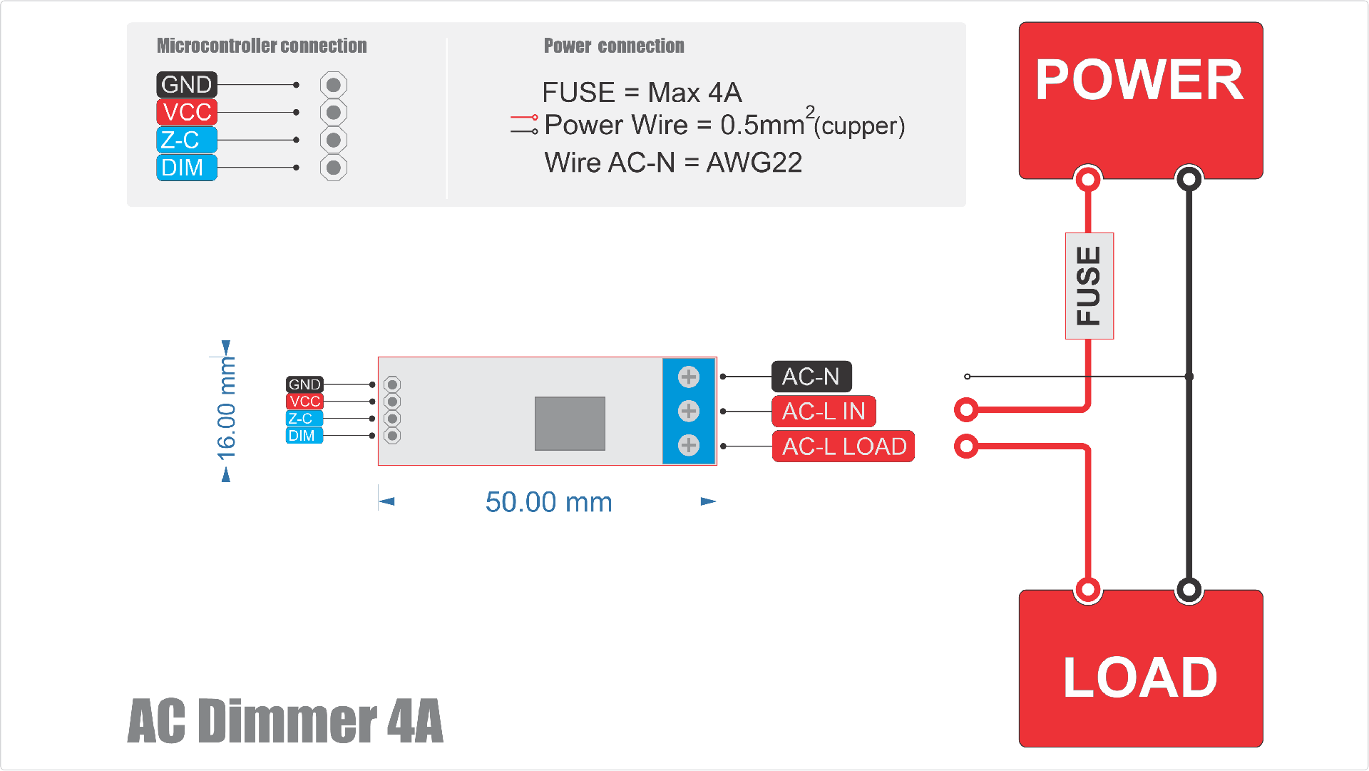
Dimmer 4A connection
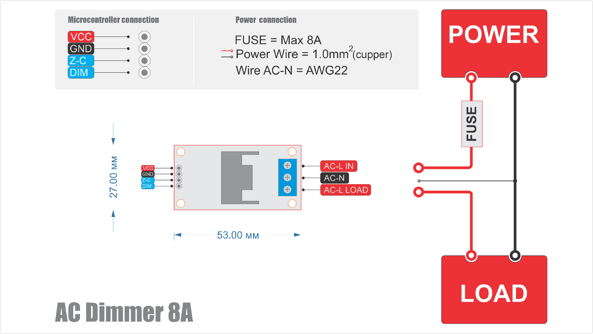
Dimmer 8A connection
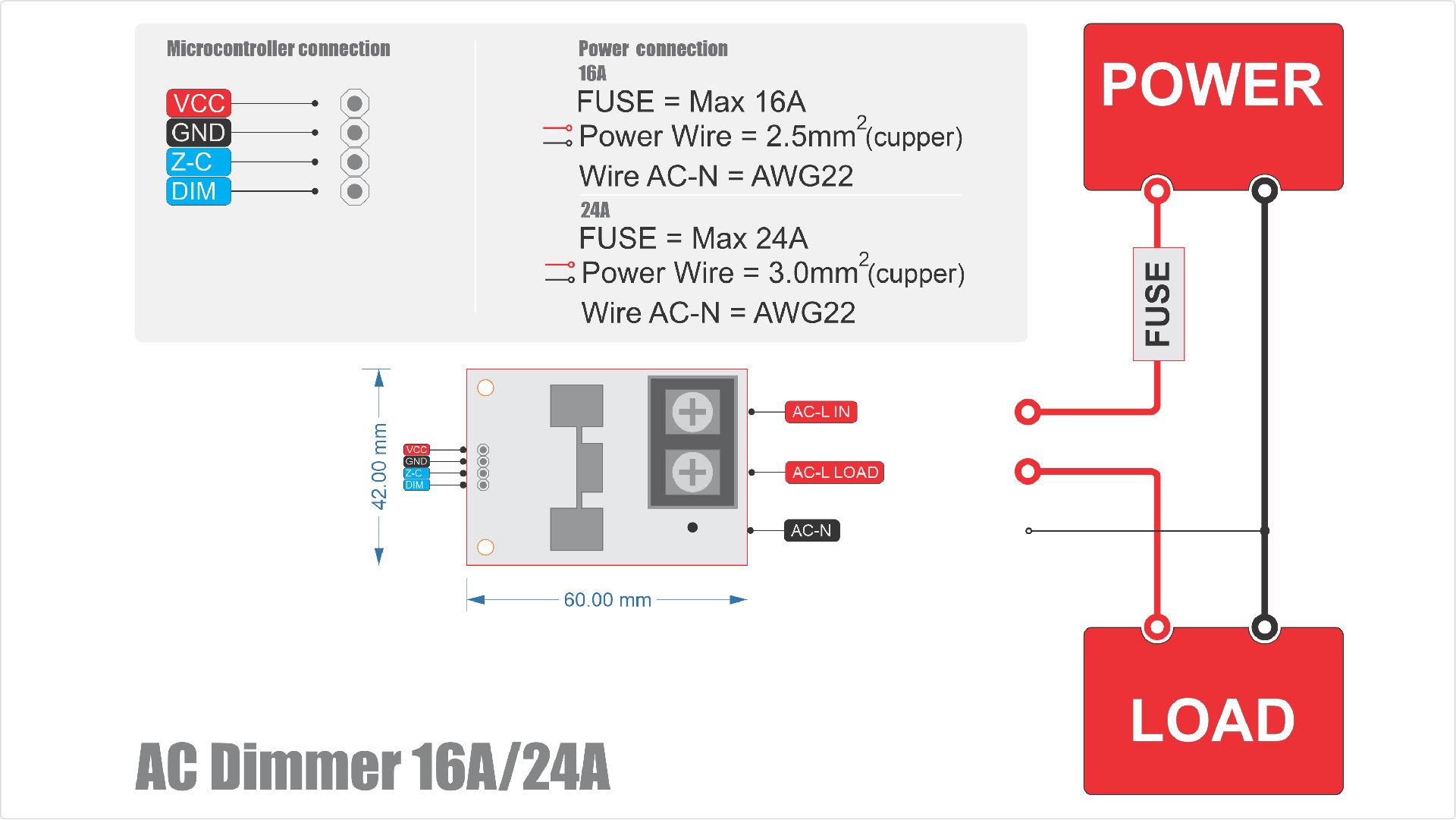
Dimmer 16/24A connection
Dimmer Module 16/24A with Temperature-Controlled Active Cooling

Dimmer Module 16/24A with Current sensor, temperature control

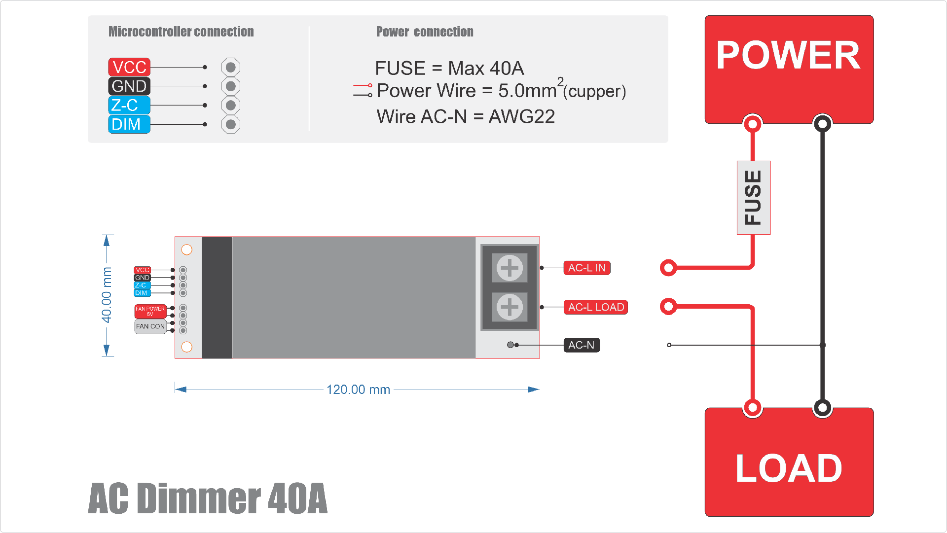
Dimmer 40A connection
AC Dimmer module 40A with Current sensor

Dimmer 8A 2 channels connection

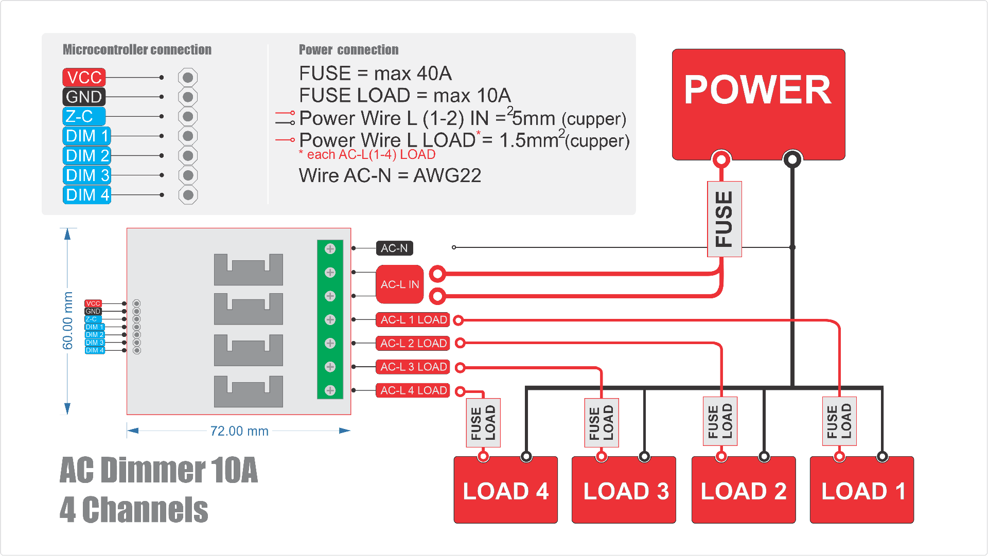
Dimmer 10A 4 channels connection
Connecting to AC Power and Load
Power Wiring
The dimmer is connected in series with the load. The live AC L-IN wire from the AC source connects to the dimmer input. The dimmer output AC L-OUT connects to the load. The neutral wire AC-N connects directly to both the zero-cross detector and the load.
Power Wires and Wire Gauge Selection
The phase wire AC L-IN, which carries power through the dimmer to the load AC L-OUT, must be sized for the maximum RMS current.
Wire Gauge Calculation
Use these formulas to determine the minimum cross-section:
- Copper wire:
S (mm²) = I (A) / 8 - Aluminum wire:
S (mm²) = I (A) / 5
These formulas are based on safe current density and heat dissipation (Joule–Lenz law):
P = I² × R, where R = ρ × L / S
Where:
P= heat (W)I= current (A)R= resistance (Ohm)ρ= material resistivity (Ω·mm²/m)L= wire length (m)S= wire cross-section (mm²)
Wire Gauge Table
If you're unfamiliar with these formulas, refer to the table below:
| Dimmer Rating | Copper Wire Min. Cross-Section | Aluminum Wire Min. Cross-Section |
|---|---|---|
| 4A | 0.5 mm² | 0.8 mm² |
| 8A | 1.0 mm² | 1.6 mm² |
| 10A | 1.5 mm² | 2.0 mm² |
| 16A | 2.5 mm² | 4.0 mm² |
| 24A | 3.0 mm² | 5.0 mm² |
| 40A | 5.0 mm² | 8.0 mm² |
Recommended Wire Type
Copper wire is strongly recommended for most dimmer-based projects due to:
- Better conductivity (ρ = 0.0175 Ω·mm²/m)
- Flexibility and long lifespan
- Oxidation resistance
Aluminum wire may be used in some cases but:
- Has higher resistivity (ρ = 0.028 Ω·mm²/m)
- Requires special connectors
- Not suitable for flexible connections
Neutral Wire (AC-N) for Zero-Cross
The neutral wire connected to the zero-cross detector carries very little current (typically 5-10 mA). It does not power the load, so it can be much thinner.
Recommended size: 0.25-0.5 mm² or AWG22, standard for signal wires.
Circuit Protection
Choosing a Fuse
Every high-voltage circuit must include a fuse:
- Prevents damage from shorts or wiring errors
- Protects against water/dust-related faults
- Prevents overload damage to the dimmer
Fuse Rating Calculation
Use the following formula:
I(fuse) = I(load) × 1.25
Do not exceed the dimmer's rated current.
Example: 1000W load at 220V = 4.5A
4.5A × 1.25 = 5.6A→ Choose a 6A fuse
Fuse vs Circuit Breaker
| Fuses | Circuit Breakers |
|---|---|
| Inexpensive | More expensive |
| Fast-acting and reliable | Resettable |
| Must be replaced after tripping | Convenient |
If using breakers, choose a quality brand for fast response.
Fuse Placement
Place the fuse before the dimmer on the AC L-IN wire.
For added safety, a second fuse may be added after the dimmer AC L-OUT if your load is sensitive or prone to shorts.
General Wiring Recommendations
When connecting a load, always ensure that all electrical connections are securely insulated. Use terminal blocks or dedicated wire connectors. Never leave exposed wire ends, especially when working with high-voltage circuits.
Insulation and Grounding
- Always place the dimmer and all electrical connections inside an insulated enclosure that prevents accidental contact
- If your device has a metal enclosure, it must be connected to protective earth (ground)
- Use insulation materials rated for at least 400V to ensure proper safety margins
Safety Guidelines
High-Voltage Warning
Always follow these essential safety rules:
- Never work on a device while it is connected to the power supply
- Always make sure the device is unplugged before beginning any work
- Use tools with insulated handles
- Do not touch bare wires or live contacts
- Never operate or assemble the dimmer in humid or dusty environments
If your device must be used outdoors or in harsh conditions, use an enclosure rated at IP67 or higher to ensure protection from moisture and dust.
Connecting to a Microcontroller
Connecting the Zero-Cross (Z-C) Output to an Interrupt Pin
The zero-cross detection Z-C output must be connected to a microcontroller pin that supports external interrupts. This allows the microcontroller to detect the exact moment the AC signal crosses zero and respond immediately.
- Arduino (ATmega): Use digital pins 2 or 3 (e.g., on Uno or Nano boards)
- ESP8266: Most GPIO pins support interrupts — nearly any can be used
- ESP32: Any GPIO pin can be used for interrupts
Connecting the Dimmer Pins (DIM)
The Dim control pin DIM can be connected to any available GPIO on the microcontroller.
Refer to the table below for recommended GPIO pins for various microcontroller families.
| Board | Pin Zero Cross (Z-C) | Pin Dim (DIM) |
|---|---|---|
| Leonardo | D7 (NOT CHANGEABLE) | D0-D6, D8-D13 |
| Mega | D2 (NOT CHANGEABLE) | D0-D1, D3-D70 |
| UNO / NANO | D2 (NOT CHANGEABLE) | D0-D1, D3-D20 |
| ESP8266 | D1(GPIO5), D5(GPIO14), D7(GPIO13), D2(GPIO4), D6(GPIO12), D8(GPIO15) | D0(GPIO16), D2(GPIO4), D6(GPIO12), D8(GPIO15), D1(GPIO5), D5(GPIO14), D7(GPIO13) |
| ESP32 | GPIO: 36, 39, 32, 25, 27, 12, 7, 2, 4, 17, 18, 21, 22, 34, 35, 33, 26, 14, 13, 15, 0, 16, 5, 19, 1, 23 | GPIO: 32, 25, 27, 12, 15, 0, 16, 5, 19, 3, 22, 33, 26, 14, 13, 2, 4, 17, 18, 21, 1, 23 |
| Arduino M0 / Arduino Zero | D7 (NOT CHANGEABLE) | D0-D6, D8-D13 |
| Arduino Due | D0-D53 | D0-D53 |
| STM32, Blue Pill (STM32F1) | PA0-PA15, PB0-PB15, PC13-PC15 | PA0-PA15, PB0-PB15, PC13-PC15 |
VCC Power Requirements
The logic power supply VCC for the dimmer must match the logic level of your microcontroller — not the main power supply used in your project.
| Microcontroller | Recommended VCC |
|---|---|
| ATmega (e.g., Uno, Nano, Mega) | 5V or 3.3V (depending on your project's logic level) |
| ESP8266 | 3.3V |
| ESP32 | 3.3V (or 1.8V in low-voltage designs) |
| STM32 | 3.3V |
Dimmer Versions with Cooling Fan
For dimmers that include a fan, the fan is powered by DC 5V.
Dimmer Versions with Temperature Control
Temperature Sensor Pin (TEMP)
If your dimmer includes a built-in temperature sensor, connect its TEMP output to an analog input (ADC pin) on your microcontroller.
Fan Control Pin (FAN)
The fan control input can be connected to any GPIO on your microcontroller.
Temperature-monitored dimmers can track the temperature of their power stage and automatically prevent overheating or hardware failure.
The official software library for this dimmer model includes:
- Dynamic fan speed control based on real-time temperature
- Critical temperature alerts
Jumper Wire Recommendations
- Avoid routing jumper wires near or across AC lines
- Do not touch jumper wires during operation, as your body can introduce electrical noise or distort signals
Next, let's move on to writing your code and integrating the library or software components.