1. Hardware Guide for DIY Developers
1.1 Overview
ACRouter can be built using two different hardware approaches, depending on your requirements, budget, and experience level.
Build Options at a Glance
| Aspect | Option 1: Controller Board | Option 2: Modular Build |
|---|---|---|
| Complexity | Plug-and-play | Requires wiring |
| Cost | Higher upfront | Lower, incremental |
| Flexibility | Fixed pinout | Customizable |
| Form Factor | Compact, integrated | Distributed modules |
| Best For | Quick deployment | Learning, customization |
| Safety | Production-grade isolation | Depends on assembly |
Both approaches are fully supported by the firmware and provide identical functionality.
Minimum Required Components
Regardless of which option you choose, a functional Solar Router requires:
- ESP32 microcontroller (integrated or separate)
- Voltage sensor (ZMPT107-based)
- Zero-cross detector (for dimmer synchronization)
- At least one current sensor (Grid current for AUTO/ECO modes)
- At least one AC dimmer (for load control)
Hardware Independence
ACRouter firmware is hardware-agnostic.
Any ESP32-compatible board and equivalent sensors can be used,
as long as electrical characteristics and safety requirements are met.
The provided controller board and reference modules serve as
validated examples and simplify wiring.
1.2 Option 1: AC Power Router Controller Board
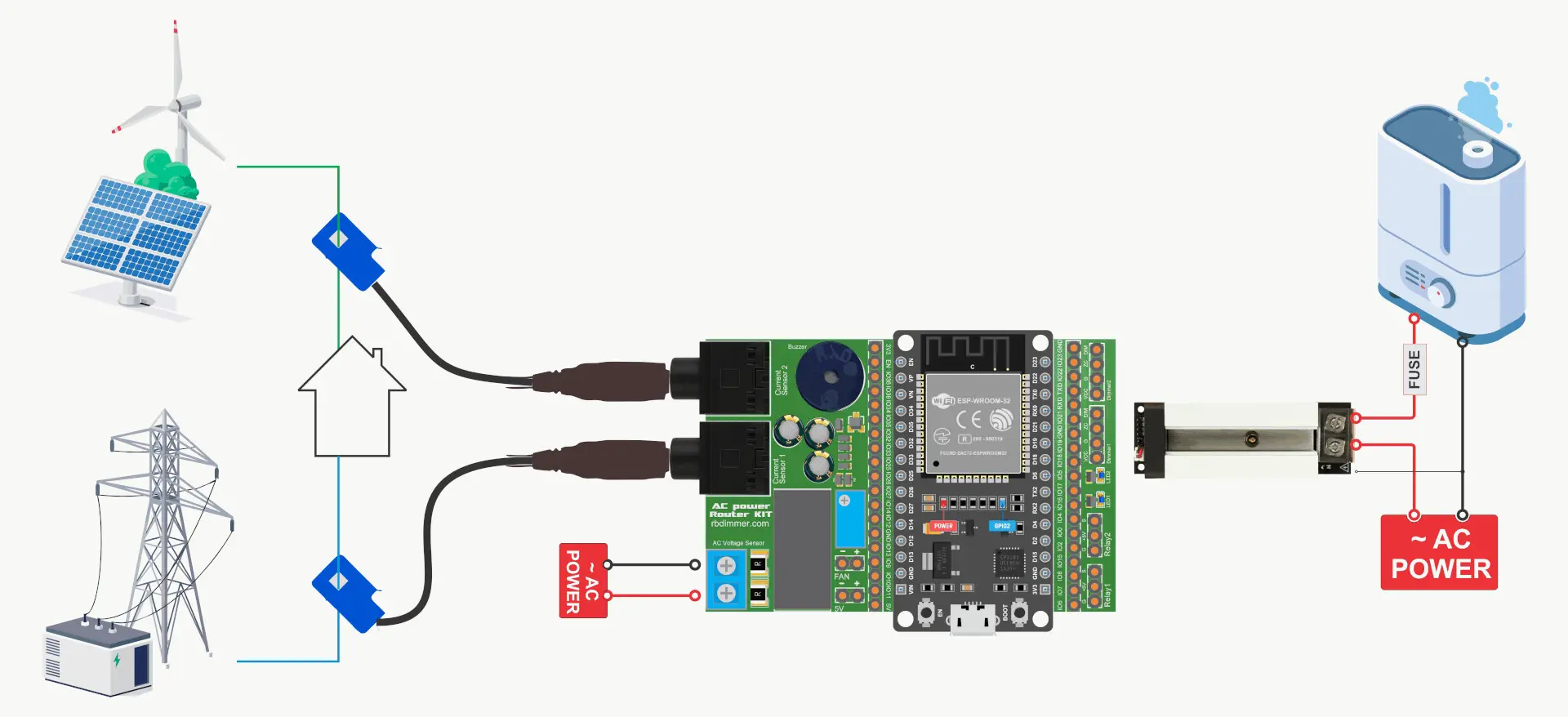
Overview
The AC Power Router Controller is an all-in-one development board based on the ESP32 microcontroller (WROOM/WROVER). It's designed for building AC dimmer and relay control systems without the complexity of breadboarding mains voltage circuits.
Ideal for: Quick deployment, ready-to-use, users who prefer integrated solutions.
What's On Board
┌─────────────────────────────────────────────────────────────────┐
│                 AC Power Router Controller                      │
│  ┌─────────────────────────────────────────────────────────┐    │
│  │                    ESP32-WROOM-32                       │    │
│  └─────────────────────────────────────────────────────────┘    │
│                                                                 │
│  ┌──────────────┐  ┌──────────────┐  ┌──────────────────────┐   │
│  │ ZMPT107      │  │ Current      │  │ Current              │   │
│  │ Voltage      │  │ Sensor 1     │  │ Sensor 2             │   │
│  │ Sensor       │  │ (3.5mm JACK) │  │ (3.5mm JACK)         │   │
│  │ [Screw Term] │  │              │  │                      │   │
│  └──────────────┘  └──────────────┘  └──────────────────────┘   │
│                                                                 │
│  ┌────────────┐  ┌────────────┐  ┌────────────┐  ┌──────────┐   │
│  │ Dimmer 1   │  │ Dimmer 2   │  │ Relay 1    │  │ Relay 2  │   │
│  │ Header     │  │ Header     │  │ Header     │  │ Header   │   │
│  │ (4-pin)    │  │ (4-pin)    │  │ (3-pin)    │  │ (3-pin)  │   │
│  └────────────┘  └────────────┘  └────────────┘  └──────────┘   │
│                                                                 │
│  [LED1] [LED2] [BUZZER]    [MicroUSB]    [5V Header]            │
│                                                                 │
│  ══════════════════════════════════════════════════════════════ │
│              GPIO Breakout Headers (all ESP32 pins)             │
│  ══════════════════════════════════════════════════════════════ │
└─────────────────────────────────────────────────────────────────┘
Features
Load Control:
- 2× AC dimmer connections (4-pin headers with Zero-Cross signal)
- 2× Relay module connections (3-pin headers)
- Support for dimmers with integrated current sensors
Power Monitoring:
- Onboard ZMPT107 voltage sensor with screw terminal
- 2× 3.5mm JACK sockets for SCT-013 current transformers
- Real-time power calculation capability
- Current limiting and overload protection support
Feedback & Alerts:
- 2× Status LEDs for visual indication
- Piezo buzzer for audio alerts
Power Supply:
- Onboard 3.3V voltage regulator
- MicroUSB socket Only for power
- Pin header for external 5V power input
Expandability:
- All ESP32 GPIOs broken out to pin headers
- Easy integration with additional sensors and modules
Pin Assignment
| GPIO | Function | Type | Notes |
|---|---|---|---|
| IO35 | AC Voltage Sensor | ADC Input | ZMPT107, onboard |
| IO39 | AC Current Sensor 1 | ADC Input | 3.5mm JACK socket |
| IO36 | AC Current Sensor 2 | ADC Input | 3.5mm JACK socket |
| IO18 | Zero-Cross Detection | Digital Input | Directly from voltage sensor |
| IO19 | Dimmer 1 Output | Digital Output | Phase control signal |
| IO23 | Dimmer 2 Output | Digital Output | Phase control signal |
| IO15 | Relay 1 | Digital Output | Active HIGH |
| IO2 | Relay 2 | Digital Output | Active HIGH, shared with onboard LED |
| IO4 | Buzzer | PWM Output | Piezo buzzer |
| IO17 | LED 1 | Digital Output | Status indicator |
| IO5 | LED 2 | Digital Output | Status indicator |
Connector Pinouts
Dimmer Headers (4-pin, ×2):
Pin 1: VCC (3.3V)
Pin 2: GND
Pin 3: ZC (Zero-Cross signal from IO18)
Pin 4: DIM (Dimmer control: IO19 or IO23)
Relay Headers (3-pin, ×2):
Pin 1: GND
Pin 2: VCC (5V)
Pin 3: RL (Relay signal: IO15 or IO2)
Current Sensor Sockets (3.5mm Stereo JACK):
Tip:    Signal output
Ring:   VCC (bias voltage)
Sleeve: GND
Wiring Diagram
                              AC MAINS (L-N)
                                   │
        ┌──────────────────────────┼─────────────────────────┐
        │                          │                         │
        │    ┌─────────────────────┴─────────────────────┐   │
        │    │         AC Power Router Controller        │   │
        │    │                                           │   │
        │    │  ┌───────────┐                            │   │
        │    │  │ ZMPT107   │◄── AC Voltage Input        │   │
        │    │  │ (onboard) │    (Screw Terminal)        │   │
        │    │  └───────────┘                            │   │
        │    │                                           │   │
        │    │  ┌───────────┐   ┌───────────┐            │   │
        │    │  │ JACK 1    │   │ JACK 2    │            │   │
        │    │  │ (Grid CT) │   │ (Solar CT)│            │   │
        │    │  └─────┬─────┘   └─────┬─────┘            │   │
        │    │        │               │                  │   │
        │    └────────┼───────────────┼──────────────────┘   │
        │             │               │                      │
        │      ┌──────┴──────┐ ┌──────┴──────┐               │
        │      │  SCT-013    │ │  SCT-013    │               │
        │      │  (Grid)     │ │  (Solar)    │               │
        │      └──────┬──────┘ └──────┬──────┘               │
        │             │               │                      │
        │         ════╪═══════════════╪════                  │
        │         Grid Line       Solar Line                 │
        │                                                    │
        │                                                    │
        │    ┌────────────────────────────────────────┐      │
        │    │         AC Dimmer Module               │      │
        │    │  ┌────────┐                            │      │
        │    │  │ 4-pin  │◄── From Dimmer Header      │      │
        │    │  │ Input  │    (VCC, GND, ZC, DIM)     │      │
        │    │  └────────┘                            │      │
        │    │                                        │      │
        │    │  AC IN ○───────────────○ AC OUT        │      │
        │    └───────┼────────────────┼───────────────┘      │
        │            │                │                      │
        └────────────┘                │                      │
                                      │                      │
                               ┌──────┴──────┐               │
                               │    LOAD     │               │
                               │  (Heater)   │               │
                               └──────┬──────┘               │
                                      │                      │
                                      └──────────────────────┘
                                              Neutral
Quick Start
- Power the board via MicroUSB or 5V header
- Connect AC voltage to the screw terminal (L-N)
- Clip current transformers around the wires you want to monitor
- Connect dimmer module to the 4-pin header
- Flash firmware via USB-UART module
- Configure via web interface or serial commands
1.3 Option 2: Modular Build with ESP32 Dev Board
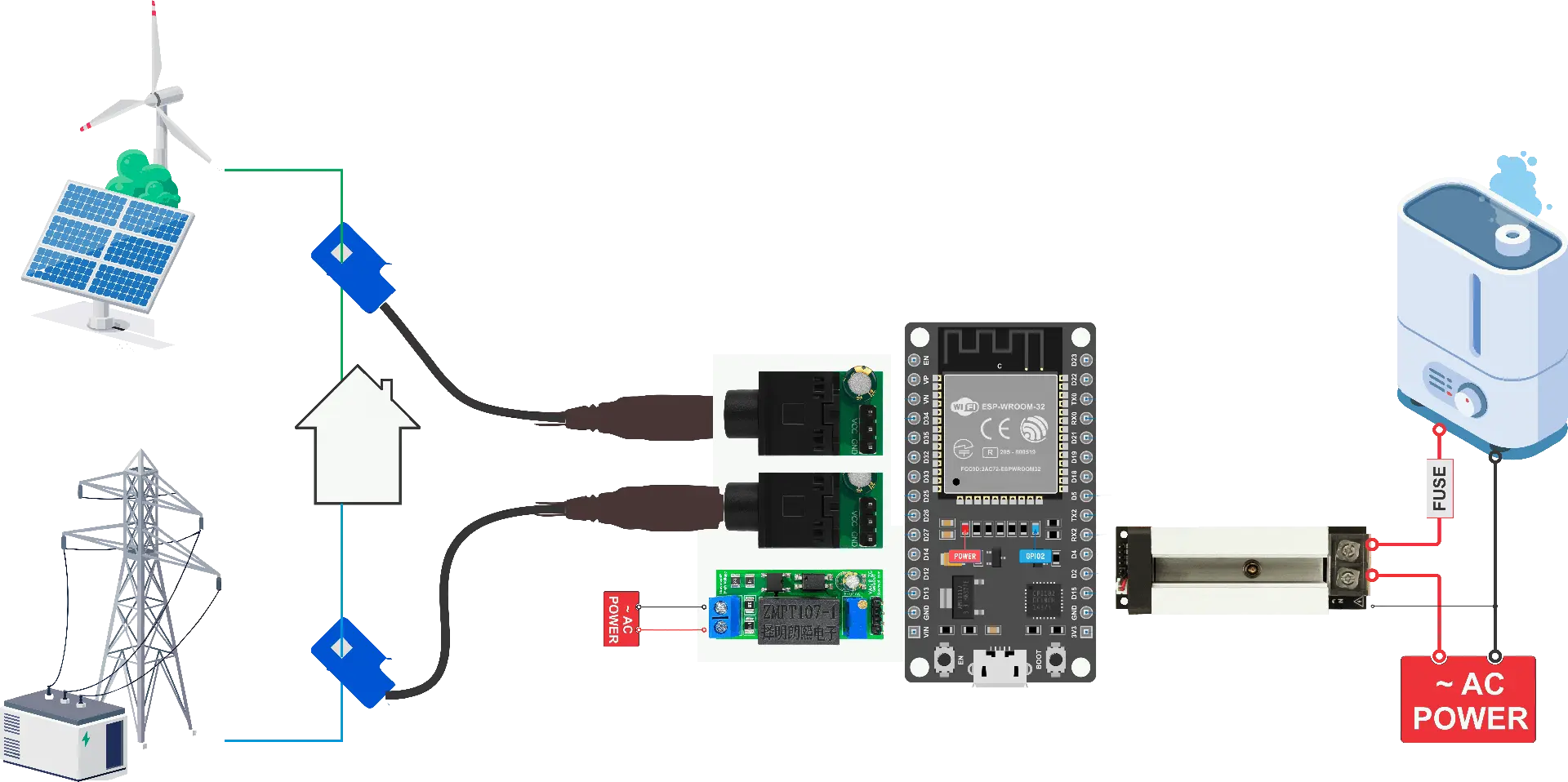
Overview
Build your own Solar Router using separate modules connected to a standard ESP32 development board. This approach offers maximum flexibility and is ideal for learning or custom installations.
Ideal for: DIY enthusiasts, custom projects, learning electronics, budget builds.
Required Modules
| Module | Purpose | Quantity |
|---|---|---|
| ESP32 DevKit | Main controller | 1 |
| Zero-Cross & Voltage Sensor | Grid voltage + sync | 1 |
| Current Sensor(s) | Power monitoring | 1-4 |
| AC Dimmer | Load control | 1-2 |
System Architecture
┌─────────────────────────────────────────────────────────────────┐
│                        ESP32 DevKit                             │
│  ┌───────────────────────────────────────────────────────────┐  │
│  │                                                           │  │
│  │   3.3V ──────┬──────┬──────┬──────┐                       │  │
│  │              │      │      │      │                       │  │
│  │   GND ───────┼──────┼──────┼──────┼──┐                    │  │
│  │              │      │      │      │  │                    │  │
│  │   GPIO36 ────┼──────┼──────┼──────┼──┼──► Voltage ADC     │  │
│  │              │      │      │      │  │                    │  │
│  │   GPIO39 ────┼──────┼──────┼──────┼──┼──► Current 1 ADC   │  │
│  │              │      │      │      │  │                    │  │
│  │   GPIO34 ────┼──────┼──────┼──────┼──┼──► Current 2 ADC   │  │
│  │              │      │      │      │  │                    │  │
│  │   GPIO18 ────┼──────┼──────┼──────┼──┼──► Zero-Cross IN   │  │
│  │              │      │      │      │  │                    │  │
│  │   GPIO19 ────┼──────┼──────┼──────┼──┼──► Dimmer OUT      │  │
│  │              │      │      │      │  │                    │  │
│  └──────────────┼──────┼──────┼──────┼──┼────────────────────┘  │
└─────────────────┼──────┼──────┼──────┼──┼───────────────────────┘
                  │      │      │      │  │
         ┌────────┘      │      │      │  └────────┐
         │               │      │      │           │
         ▼               ▼      ▼      ▼           ▼
    ┌─────────┐    ┌─────────┐ ┌─────────┐   ┌─────────┐
    │ ZC+Volt │    │ Current │ │ Current │   │ Dimmer  │
    │ Module  │    │ Sensor 1│ │ Sensor 2│   │ Module  │
    └─────────┘    └─────────┘ └─────────┘   └─────────┘
         │              │           │             │
         ▼              ▼           ▼             ▼
      AC Mains      Grid Line   Solar Line      Load
1.4 Zero-Cross & Voltage Sensor Module
Overview
This specialized module combines a precision voltage sensor (ZMPT107-1 transformer) with a high-speed Zero-Cross detector. The Zero-Cross signal is essential for proper dimmer synchronization. Zero-cross signal timing accuracy directly affects dimmer stability and EMC performance.
Specifications
Voltage Measurement:
- Transformer: ZMPT107-1 (2mA/2mA ratio)
- Range: 0-250V AC
- Accuracy: ±0.5%
- Output: 0-3.3V analog (centered at 1.65V DC)
Zero-Cross Detector:
- Circuit: Diode bridge + PC817 optocoupler
- Response time: <100 µs
- Output: Digital 3.3V (active LOW pulse)
- Frequency: 100Hz (50Hz mains) or 120Hz (60Hz mains)
General:
- Supply voltage: 3.3V DC
- Current draw: <20 mA
- Isolation: 4000V RMS
- Operating temperature: -20°C to +70°C
- Dimensions: 46.5 × 18.5 × 20 mm
Features
- Trimmer potentiometer for measurement range adjustment
- Factory calibrated, ready to use
- Galvanic isolation for safety
- Mains current draw: <0.5 mA
Connection to ESP32
Module Pin    ESP32 Pin       Function
──────────    ─────────       ────────
GND           GND             Common ground
VCC           3.3V            Module power
VOUT          GPIO35/36       Voltage sensor analog output
ZC            GPIO18          Zero-cross digital output
AC Connection
        AC MAINS
           │
    L ─────┤
           │    ┌─────────────────────┐
           ├────┤ AC Input Terminal   │
           │    │                     │
    N ─────┤    │  ZC+Voltage Module  │
           │    │                     │
           └────┤                     │
                └─────────────────────┘
Wire gauge: AWG-26 or higher recommended.
What You Can Monitor
With just the Zero-Cross & Voltage Sensor module:
- Grid voltage (RMS)
- Mains frequency (50/60 Hz)
- Voltage quality analysis
- Basic grid status
- Dimmer synchronization
Note: Current sensors are required for power calculations.
1.5 Current Sensors
Current sensors complete your monitoring system, enabling full power analysis, energy tracking, and cost calculations. Two technologies are available.
Option A: ACS-712 Hall-Effect Sensors
Technology: Hall effect, measures magnetic field around conductor
Installation: Requires breaking the circuit (wire passes through sensor)
Best for: New installations, maximum accuracy, bidirectional current measurement
Available Models
| Model | Range | Sensitivity | Resolution | Best For |
|---|---|---|---|---|
| ACS712-5A | ±5A | 185 mV/A | 26 mA | Small electronics |
| ACS712-10A | ±10A | 100 mV/A | 49 mA | LED lighting |
| ACS712-20A | ±20A | 100 mV/A | 49 mA | Home appliances |
| ACS712-30A | ±30A | 66 mV/A | 74 mA | HVAC, heating |
| ACS712-50A | ±50A | 40 mV/A | 122 mA | Main supply, solar |
Specifications
- Measurement type: DC/AC (True RMS with ACRouter)
- Supply voltage: 5V DC ±5%
- Current consumption: 10-13 mA
- Output signal: 0-3.3V (centered at 1.65V at zero current)
- Bandwidth: 80 kHz
- Response time: 5 µs
- Isolation: 2.1 kV RMS
- Accuracy: ±1.5%
- Current path resistance: 1.2 mΩ
- Overload protection: Up to 5× rated current
Connection to ESP32
ACS712 Pin    ESP32 Pin       Notes
──────────    ─────────       ─────
GND           GND             Common ground
VCC           5V              Requires 5V supply
OUT           GPIO32-39       ADC1 pins only!
Important: Use only ADC1 pins (GPIO32, 33, 34, 35, 36, 39) as ADC2 conflicts with WiFi.
Wiring Diagram
                    Current Flow Direction
                    ─────────────────────►

    ┌─────────────────────────────────────────────┐
    │                 ACS712 Module               │
    │                                             │
    │   IP+ ○─────────────────────────○ IP-       │
    │        │                       │            │
    │        │    ┌───────────┐     │             │
    │        └────┤ Hall      ├─────┘             │
    │             │ Sensor    │                   │
    │             └─────┬─────┘                   │
    │                   │                         │
    │   GND ○     VCC ○ │  OUT ○                  │
    └─────┼───────┼─────┼────┼────────────────────┘
          │       │     │    │
          │       │     │    └──► To ESP32 ADC
          │       │     │
          │       └─────┴──────► To ESP32 5V & GND
          │
          └──────────────────► To ESP32 GND
Option B: SCT-013 Current Transformers
Technology: Electromagnetic induction, clip-on transformer
Installation: Non-invasive, clips around existing wire without cutting
Best for: Retrofitting, existing installations, rental properties
Available Models
| Model | Range | Output | Best For |
|---|---|---|---|
| SCT-013-010 | 0-10A | 0-1V | Individual circuits |
| SCT-013-030 | 0-30A | 0-1V | Standard home circuits |
| SCT-013-050 | 0-50A | 0-1V | Main supply, large appliances |
| SCT-013-100 | 0-100A | 0-50mA | Industrial, whole building |
Note: The SCT-013-100 outputs current (50mA), not voltage. It requires an external burden resistor. Other models have built-in burden resistors and output voltage directly.
SCT-013 Adapter Module
The adapter module provides signal conditioning for connecting SCT-013 transformers to ESP32:
Features:
- 3.5mm stereo jack socket for SCT-013
- Precision voltage divider (creates 1.65V DC bias)
- AC coupling capacitor
- Noise filtering
- 0-3.3V output compatible with ESP32 ADC
Connection to ESP32:
Adapter Pin    ESP32 Pin       Function
───────────    ─────────       ────────
GND            GND             Common ground
VCC            3.3V            Module power (3.3V!)
SIG            GPIO32-39       ADC1 pins only
Wiring Diagram
                Wire to Monitor
                ═══════════════════
                       │
                ┌──────┴──────┐
                │  SCT-013    │
                │  ┌──────┐   │
                │  │      │   │  (Clip around wire,
                │  │  CT  │   │   don't cut it!)
                │  │      │   │
                │  └───┬──┘   │
                │      │      │
                └──────┼──────┘
                       │
                  3.5mm Plug
                       │
                ┌──────┴──────┐
                │   Adapter   │
                │   Module    │
                │             │
                │ GND VCC SIG │
                └──┬───┬───┬──┘
                   │   │   │
                   │   │   └──► ESP32 GPIO (ADC1)
                   │   └──────► ESP32 3.3V
                   └──────────► ESP32 GND
Sensor Selection Guide
| Requirement | Recommended Sensor |
|---|---|
| New installation, maximum accuracy | ACS-712 |
| Existing installation, no rewiring | SCT-013 + Adapter |
| Bidirectional current (grid import/export) | ACS-712 (any) or SCT-013 |
| Solar surplus routing | SCT-013 or ACS712 (bidirectional) |
| High current (>50A) | SCT-013-100 |
| Low current precision (<5A) | ACS-712-5A |
| Budget-conscious build | SCT-013-030 + Adapter |
| Professional/production use | ACS-712 or Controller Board |
1.6 AC Dimmer Modules
AC dimmer modules control power to resistive loads (heaters, incandescent bulbs) using phase-cut dimming synchronized with the Zero-Cross signal.
Compatible Dimmers
ACRouter is designed to work with RBDimmer modules, which provide:
- TRIAC-based phase control
- Built-in zero-cross detection input
- Optocoupler isolation
- Snubber circuit for inductive noise suppression
Connection Interface
Standard 4-pin connection:
Pin    Function        Description
───    ────────        ───────────
1      VCC (3.3V)      Logic power supply
2      GND             Common ground
3      ZC              Zero-Cross input (from sensor module)
4      DIM             Dimmer control signal (from ESP32)
Wiring Diagram
                         ┌─────────────────────────────────────┐
    From ZC+Volt Module  │           AC Dimmer Module          │
    ┌────────────────────┤                                     │
    │                    │  VCC ○────────────────────┐         │
    │   ZC Signal ───────┤► ZC  ○                    │         │
    │                    │                           │         │
    │   From ESP32       │  DIM ○◄───────────────────┼─────────┤── GPIO19
    │   ┌────────────────┤                           │         │
    │   │                │  GND ○────────────────────┼─────────┤── GND
    │   │                │                           │         │
    │   │                │                           └─────────┤── 3.3V
    │   │                │                                     │
    │   │                │  AC IN ○──────────┬───────○ AC OUT  │
    │   │                │                   │                 │
    │   │                └───────────────────┼─────────────────┘
    │   │                                    │
    │   │                                  TRIAC
    │   │                                    │
    │   │                                    │
────┴───┴────────────────────────────────────┴─────────────────────
    AC MAINS (Live)                                          LOAD
                                                           (Heater)
────────────────────────────────────────────────────────────────────
    AC MAINS (Neutral)
Dimmer Control Principle
- Zero-Cross Detection: ZC signal pulses at every AC zero crossing (100Hz for 50Hz mains)
- Phase Delay: ESP32 waits for calculated delay time after zero-cross
- TRIAC Trigger: Short pulse (10-100µs) triggers TRIAC
- Conduction: TRIAC conducts until next zero-cross
- Power Control: Longer delay = less power, shorter delay = more power
AC Waveform:
    ╭───╮       ╭───╮       ╭───╮
   ╱     ╲     ╱     ╲     ╱     ╲
──╱───────╲───╱───────╲───╱───────╲──
            ╲╱         ╲╱         ╲╱
             ╰───╯       ╰───╯

ZC Pulses:   │         │         │
            ─┴─       ─┴─       ─┴─

50% Power (delay = 5ms for 50Hz):
    ╭───╮       ╭───╮       ╭───╮
   ╱░░░░░╲     ╱░░░░░╲     ╱░░░░░╲
──╱───────╲───╱───────╲───╱───────╲──
     ▲         ▲         ▲
     │         │         │
   Trigger   Trigger   Trigger
Supported Loads
Compatible (resistive loads):
- ✅ Water heater elements (ТЭН)
- ✅ Space heaters
- ✅ Incandescent bulbs
- ✅ Heating mats
- ✅ Resistive heating cables
NOT compatible:
- ❌ Motors (fans, pumps)
- ❌ LED drivers
- ❌ Switching power supplies
- ❌ Fluorescent lights
- ❌ Inductive loads
Power Ratings
Typical dimmer module ratings:
| Module | Max Current | Max Power (230V) | Max Power (110V) |
|---|---|---|---|
| 2A | 2A | 460W | 220W |
| 4A | 4A | 920W | 440W |
| 8A | 8A | 1840W | 880W |
| 16A | 16A | 3680W | 1760W |
Important: Derate by 20-30% for continuous operation. A 2kW heater should use at least an 8A (1840W) dimmer.
1.7 Complete Wiring Examples
Minimal Configuration (AUTO Mode)
For basic Solar Router operation, you need:
- Voltage measurement
- Grid current measurement
- One dimmer
┌─────────────────────────────────────────────────────────────────┐
│                          ESP32 DevKit                           │
│                                                                 │
│    3.3V ─────┬────────────────────┬──────────────────────────   │
│              │                    │                             │
│    GND ──────┼────────────────────┼────────────────────┬────────│
│              │                    │                    │        │
│    GPIO35 ───┼────────────────────┼──► (Voltage ADC)   │        │
│              │                    │                    │        │
│    GPIO36 ───┼────────────────────┼──► (Grid Cur ADC)  │        │
│              │                    │                    │        │
│    GPIO18 ───┼──► (Zero-Cross IN) │                    │        │
│              │                    │                    │        │
│    GPIO19 ───┼────────────────────┼────────────────────┼─► (DIM)│
│              │                    │                    │        │
└──────────────┼────────────────────┼────────────────────┼────────┘
               │                    │                    │
       ┌───────┴───────┐    ┌───────┴───────┐    ┌──────┴───────┐
       │   ZC+Volt     │    │  SCT-013      │    │   Dimmer     │
       │   Module      │    │  + Adapter    │    │   Module     │
       │               │    │               │    │              │
       │ VCC GND ZC OUT│    │ VCC GND SIG   │    │VCC GND ZC DIM│
       └───┬───┬───┬───┘    └───┬───┬───────┘    └──┬──┬──┬──┬──┘
           │   │   │            │   │               │  │  │  │
           │   │   │            │   │               │  │  │  │
           │   │   └──► GPIO35  │   └──► GPIO36     │  │  │  └──► GPIO19
           │   │                │                   │  │  │
           │   └────────────────┼───────────────────┼──┘  └──► From ZC
           │                    │                   │
           └────────────────────┴───────────────────┴──► To 3.3V & GND

       ═══════════════                              ═══════════════
           AC MAINS                                     TO LOAD
       (to ZC+Volt module)                          (from Dimmer)
Full Configuration (4 Channels)
For complete monitoring with solar generation tracking:
┌────────────────────────────────────────────────────────────────┐
│                          ESP32 DevKit                          │
│                                                                │
│    3.3V ──┬────────┬────────┬────────┬─────────────────────────│
│           │        │        │        │                         │
│    5V ────┼────────┼────────┼────────┼────┬────┬───────────────│
│           │        │        │        │    │    │               │
│    GND ───┼────────┼────────┼────────┼────┼────┼────┬──────────│
│           │        │        │        │    │    │    │          │
│  GPIO35 ──┼──►Volt │        │        │    │    │    │          │
│           │        │        │        │    │    │    │          │
│  GPIO39 ──┼────────┼──►Load │        │    │    │    │          │
│           │        │        │        │    │    │    │          │
│  GPIO36 ──┼────────┼────────┼──►Grid │    │    │    │          │
│           │        │        │        │    │    │    │          │
│  GPIO34 ──┼────────┼────────┼────────┼──►Solar │    │          │
│           │        │        │        │    │    │    │          │
│  GPIO18 ──┼──►ZC   │        │        │    │    │    │          │
│           │        │        │        │    │    │    │          │
│  GPIO19 ──┼────────┼────────┼────────┼────┼──►DIM1  │          │
│           │        │        │        │    │    │    │          │
│  GPIO23 ──┼────────┼────────┼────────┼────┼────┼──►DIM2        │
│           │        │        │        │    │    │    │          │
└───────────┼────────┼────────┼────────┼────┼────┼────┼──────────┘
            │        │        │        │    │    │    │
    ┌───────┴──┐ ┌───┴───┐ ┌──┴────┐ ┌─┴────┴─┐  │    │
    │ ZC+Volt  │ │ACS712 │ │ACS712 │ │ ACS712 │  │    │
    │ Module   │ │ Load  │ │ Grid  │ │ Solar  │  │    │
    └──────────┘ └───────┘ └───────┘ └────────┘  │    │
         │           │         │         │       │    │
         │           │         │         │       │    │
    ═════╪═══════════╪═════════╪═════════╪═══════╪════╪════
    AC MAINS     Load Wire  Grid Wire Solar Wire │    │
                                                 │    │
                                         ┌───────┴────┴───────┐
                                         │  Dimmer Modules    │
                                         │  (1 and 2)         │
                                         └────────────────────┘
                                                 │
                                            TO LOADS
                                         (Heater 1 & 2)
1.8 Bill of Materials
Option 1: Controller Board Build
| Item | Quantity | Notes |
|---|---|---|
| AC Power Router Controller Board | 1 | Includes ESP32, voltage sensor |
| SCT-013-030 Current Transformer | 2-3 | For grid, solar, load monitoring |
| AC Dimmer Module (2kW+) | 1-2 | Match to your load power |
| Relay Module (optional) | 1-2 | For on/off loads |
| 5V Power Supply | 1 | 1A minimum |
| AC cables and connectors | As needed | AWG-14 or appropriate for load |
Estimated cost: $50-80 (excluding load and power supply)
Option 2: Modular Build
| Item | Quantity | Notes |
|---|---|---|
| ESP32 DevKit (WROOM or WROVER) | 1 | 4MB flash minimum |
| Zero-Cross + Voltage Sensor Module | 1 | ZMPT107-based |
| Current Sensor (choose one type): | ||
| - ACS712-30A | 2-3 | For Hall-effect sensing |
| - OR SCT-013-030 + Adapter | 2-3 | For clip-on CT sensing |
| AC Dimmer Module (2kW+) | 1-2 | RBDimmer recommended |
| Breadboard or PCB | 1 | For connections |
| Jumper wires | Set | Male-female, male-male |
| 5V Power Supply | 1 | 1A minimum |
| Enclosure (optional) | 1 | IP-rated for safety |
Estimated cost: $35-60 (excluding load and power supply)
Common Accessories
| Item | Purpose |
|---|---|
| DIN rail enclosure | Professional installation |
| Terminal blocks | Secure AC connections |
| Cable glands | Waterproof cable entry |
| Fuses/MCB | Overcurrent protection |
| Heat shrink tubing | Wire insulation |
1.9 Safety Considerations
⚠️ DANGER: Mains Voltage
AC mains voltage (110V/230V) can cause serious injury or death.
Before working with this project:
- Qualifications: Electrical work should be performed by qualified personnel
- Isolation: Always disconnect power before making connections
- Insulation: Use properly rated wire and connectors
- Protection: Install appropriate fuses, MCB, and RCD/GFCI
- Enclosure: House all mains connections in appropriate enclosures
- Testing: Verify isolation with a multimeter before applying power
Design Safety Features
Built into ACRouter firmware:
- Watchdog timer (disables outputs on crash)
- Zero-cross timeout detection (disables dimmers if AC lost)
- Overcurrent monitoring (if current sensors connected)
- Safe startup state (all outputs OFF at boot)
You must provide:
- Appropriate fusing for your loads
- RCD/GFCI protection
- Physical isolation and enclosure
- Proper wire gauge for current levels
Grounding
IMPORTANT: Proper grounding is essential for safety!

    AC MAINS
    ═══════════════════════════════════════
        L (Live/Hot)
        N (Neutral)
        PE (Protective Earth) ──────────────┐
                                            │
    All metal enclosures, frames,           │
    and exposed conductive parts ───────────┤
                                            │
    ESP32 GND (logic ground) ───────────────┤
                                            │
    Central Earth Point ◄───────────────────┘
Load Considerations
| Load Type | Max Power | Notes |
|---|---|---|
| Water heater | 2-3 kW typical | Check element rating |
| Space heater | 1-2 kW typical | Ensure resistive type |
| Heating element | Varies | Calculate: P = V²/R |
Never exceed:
- Dimmer module rating (derate 20-30%)
- Wire ampacity
- Fuse/MCB rating
- Socket/connector rating
1.10 Troubleshooting Hardware Issues
No Voltage Reading
| Symptom | Possible Cause | Solution |
|---|---|---|
| Always 0V | No AC connection | Check screw terminal |
| Always 0V | Wrong GPIO | Verify GPIO35 connection |
| Noisy/unstable | Poor connection | Tighten terminals |
| Wrong value | Needs calibration | Adjust trimmer pot |
No Current Reading
| Symptom | Possible Cause | Solution |
|---|---|---|
| Always 0A | CT not clipped | Ensure CT surrounds wire |
| Always 0A | Wrong GPIO | Use ADC1 pins only |
| Half expected | CT on wrong conductor | Clip around single wire, not cable |
| Negative value | CT direction | Reverse CT orientation |
Dimmer Not Working
| Symptom | Possible Cause | Solution |
|---|---|---|
| No output | No ZC signal | Check ZC connection |
| Full on/off only | ZC timing wrong | Verify ZC module working |
| Flickering | Kp too high | Reduce control gain |
| No change | Wrong GPIO | Verify GPIO19/23 connection |
Communication Issues
| Symptom | Possible Cause | Solution |
|---|---|---|
| No Serial | Wrong baud | Use 115200 baud |
| No WiFi AP | Not initialized | Check startup logs |
| Can't flash | Boot mode | Hold BOOT button while reset |
1.11 Where to Buy
AC Power Router Controller Board
Available at: rbdimmer.com
AliExpress: (https://robotdyn.aliexpress.com/store/1950989)
Individual Modules
Zero-Cross & Voltage Sensor:
- rbdimmer.com
- RBGrid ecosystem partners
Current Sensors:
- ACS712 modules: Amazon, AliExpress, electronics distributors
- SCT-013 transformers: Amazon, AliExpress, energy monitoring suppliers
- SCT-013 adapters: rbdimmer.com, DIY build
AC Dimmer Modules:
- rbdimmer.com (RBDimmer series)
- AliExpress: (https://robotdyn.aliexpress.com/store/1950989)
- Compatible modules from other suppliers (verify pinout)
ESP32 DevKit:
- Espressif official partners
- Amazon, AliExpress
- Electronics distributors (Mouser, DigiKey, etc.)