Hardware Connection
Wiring diagrams for connecting DimmerLink to popular microcontrollers and single-board computers.
DimmerLink Connectors
Input Connector (to your project)
| Pin |
Function |
Description |
| VCC |
Power |
1.8V, 3.3V or 5V DC |
| GND |
Ground |
Common ground |
| TX/SDA |
Data |
UART TX or I2C SDA |
| RX/SCL |
Clock |
UART RX or I2C SCL |
Output Connector (to dimmer module)
| Pin |
Function |
Description |
| VCC |
Power |
Same as input |
| GND |
Ground |
Common ground |
| Z-C |
Zero-Cross |
Zero-crossing signal |
| Dim |
Control |
TRIAC gate signal |
Compatibility
DimmerLink supports a wide range of supply voltages and logic levels:
| Voltage |
VCC Power |
Logic Levels |
| 1.8V |
✓ |
✓ |
| 3.3V |
✓ |
✓ |
| 5.0V |
✓ |
✓ |
✅ Direct connection to any microcontroller without level converters!
General Connection Diagram
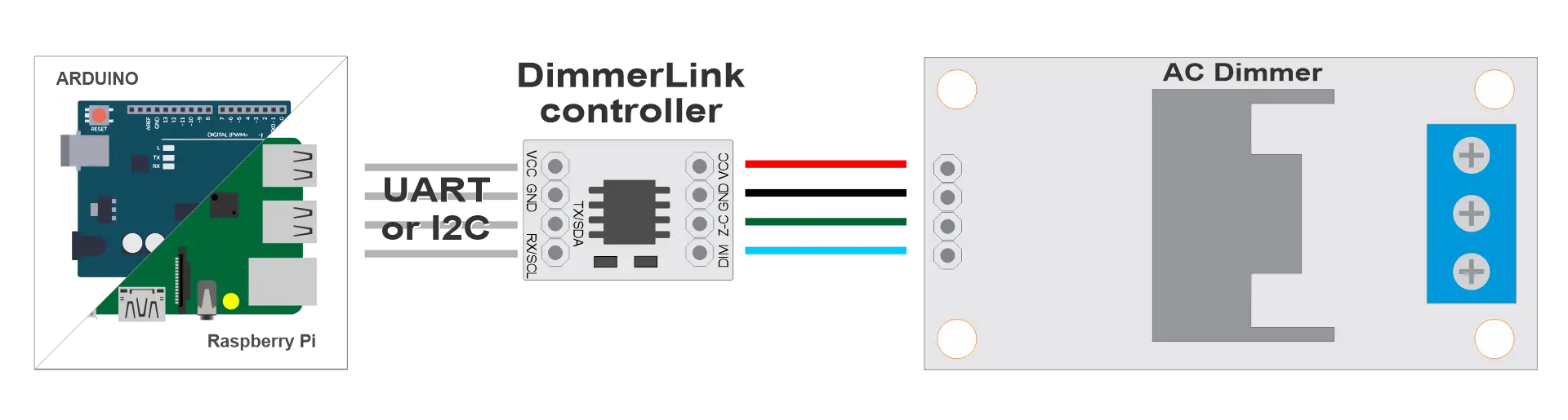
python
┌─────────────────┐      ┌──────────────────┐      ┌─────────┐      ┌──────┐
│  Your Project   │      │   DimmerLink     │      │ Dimmer  │      │ Lamp │
│  (Arduino/RPi)  │◄────►│                  │◄────►│ (TRIAC) │◄────►│      │
└─────────────────┘      └──────────────────┘      └─────────┘      └──────┘
     UART/I2C                                         AC 220V
Supported Platforms
DimmerLink works with any microcontroller that has UART or I2C interface.
| Platform |
UART |
I2C |
Logic Level |
Connection |
| Arduino Uno/Nano |
✓ |
✓ |
5V |
Direct |
| Arduino Mega |
✓ |
✓ |
5V |
Direct |
| Arduino Due |
✓ |
✓ |
3.3V |
Direct |
| ESP8266 |
✓ |
✓ |
3.3V |
Direct |
| ESP32 |
✓ |
✓ |
3.3V |
Direct |
| STM32 Blue Pill |
✓ |
✓ |
3.3V |
Direct |
| Raspberry Pi Pico |
✓ |
✓ |
3.3V |
Direct |
| Raspberry Pi 3/4/5 |
✓ |
✓ |
3.3V |
Direct |
| Orange Pi |
✓ |
✓ |
3.3V |
Direct |
| Banana Pi |
✓ |
✓ |
3.3V |
Direct |
| ATtiny, nRF52, MSP430 |
✓ |
✓ |
1.8V |
Direct |
Any controller with UART or I2C connects directly!
I2C Connection
Requirements
- Pull-up resistors: Many controllers already have I2C pull-ups. Add 4.7kΩ resistors on SDA and SCL to VCC
- Speed: 100 kHz (Standard Mode)
- Address: 0x50
I2C Wiring Diagram
python
                    VCC (your board)
                     │
                ┌────┴────┐
               4.7kΩ     4.7kΩ
                │         │
┌───────────┐   │         │   ┌──────────────────┐
│           │   │         │   │   DimmerLink     │
│   Your    │───┴─────────│───│ SDA              │
│  Project  │             │   │                  │
│   SDA     │─────────────┴───│ SCL              │
│   SCL     │                 │                  │
│   GND     │─────────────────│ GND              │
│   VCC     │─────────────────│ VCC              │
└───────────┘                 └──────────────────┘
Dimmer Connection
| DimmerLink |
Dimmer |
Description |
| VCC |
VCC |
Power (same as from MCU) |
| GND |
GND |
Common ground |
| Z-C |
Z-C (Zero Cross) |
Zero-crossing signal |
| Dim |
DIM / PWM / Gate |
TRIAC control signal |
Arduino Uno / Nano
I2C Connection
| Arduino |
DimmerLink |
| A4 (SDA) |
SDA |
| A5 (SCL) |
SCL |
| GND |
GND |
| 5V |
VCC |
UART Connection
| Arduino |
DimmerLink |
| TX (1) or SoftwareSerial |
RX |
| RX (0) or SoftwareSerial |
TX |
| GND |
GND |
| 5V |
VCC |
📝 Note: On Arduino Uno, pins 0/1 are used for USB. SoftwareSerial is recommended.
cpp
#include
SoftwareSerial dimmerSerial(10, 11);
void setup() {
dimmerSerial.begin(115200);
}
Arduino Mega
I2C Connection
| Arduino Mega |
DimmerLink |
| 20 (SDA) |
SDA |
| 21 (SCL) |
SCL |
| GND |
GND |
| 5V |
VCC |
UART Connection
| Arduino Mega |
DimmerLink |
| TX1 (18) |
RX |
| RX1 (19) |
TX |
| GND |
GND |
| 5V |
VCC |
Arduino Mega has 4 hardware UARTs (Serial, Serial1, Serial2, Serial3).
ESP8266 (NodeMCU, Wemos D1)
I2C Connection
| ESP8266 |
DimmerLink |
| D2 (GPIO4) |
SDA |
| D1 (GPIO5) |
SCL |
| GND |
GND |
| 3.3V |
VCC |
UART Connection
| ESP8266 |
DimmerLink |
| TX (GPIO1) |
RX |
| RX (GPIO3) |
TX |
| GND |
GND |
| 3.3V |
VCC |
📝 Note: GPIO1/GPIO3 are used for USB. Alternatives:
- Use Serial.swap() to remap to GPIO15/GPIO13
- Or use I2C instead of UART
ESP32
I2C Connection
| ESP32 |
DimmerLink |
| GPIO21 |
SDA |
| GPIO22 |
SCL |
| GND |
GND |
| 3.3V |
VCC |
I2C pins can be remapped:
cpp
Wire.begin(SDA_PIN, SCL_PIN);
UART Connection
| ESP32 |
DimmerLink |
| GPIO17 (TX2) |
RX |
| GPIO16 (RX2) |
TX |
| GND |
GND |
| 3.3V |
VCC |
ESP32 has 3 hardware UARTs (Serial, Serial1, Serial2).
STM32 Blue Pill
I2C Connection
| STM32 |
DimmerLink |
| PB7 (I2C1 SDA) |
SDA |
| PB6 (I2C1 SCL) |
SCL |
| GND |
GND |
| 3.3V |
VCC |
UART Connection
| STM32 |
DimmerLink |
| PA9 (USART1 TX) |
RX |
| PA10 (USART1 RX) |
TX |
| GND |
GND |
| 3.3V |
VCC |
Raspberry Pi Pico
I2C Connection
| Pico |
DimmerLink |
| GP4 (I2C0 SDA) |
SDA |
| GP5 (I2C0 SCL) |
SCL |
| GND |
GND |
| 3V3 |
VCC |
UART Connection
| Pico |
DimmerLink |
| GP0 (UART0 TX) |
RX |
| GP1 (UART0 RX) |
TX |
| GND |
GND |
| 3V3 |
VCC |
Raspberry Pi 3/4/5
I2C Connection
| Raspberry Pi |
DimmerLink |
| GPIO2 (Pin 3) |
SDA |
| GPIO3 (Pin 5) |
SCL |
| GND (Pin 6) |
GND |
| 3.3V (Pin 1) |
VCC |
Enabling I2C:
bash
sudo raspi-config
UART Connection
| Raspberry Pi |
DimmerLink |
| GPIO14 (Pin 8) |
RX |
| GPIO15 (Pin 10) |
TX |
| GND (Pin 6) |
GND |
| 3.3V (Pin 1) |
VCC |
Enabling UART:
bash
sudo raspi-config
Orange Pi / Banana Pi
Connection is similar to Raspberry Pi, but GPIO numbers may differ.
Orange Pi (e.g., Orange Pi Zero)
⚠️ Warning: GPIO pinout differs between models! Check your specific board's documentation.
General principle:
1. Find I2C pins in your board's documentation
2. Connect SDA → SDA, SCL → SCL
3. Add 4.7kΩ pull-up resistors
| Orange Pi |
DimmerLink |
| PA12 (TWI0-SDA) |
SDA |
| PA11 (TWI0-SCL) |
SCL |
| GND |
GND |
| 3.3V |
VCC |
Banana Pi (e.g., Banana Pi M2)
| Banana Pi |
DimmerLink |
| GPIO2 (Pin 3) |
SDA |
| GPIO3 (Pin 5) |
SCL |
| GND |
GND |
| 3.3V |
VCC |
📝 Note: Check documentation for your specific Orange Pi / Banana Pi model.
I2C Pull-up Resistors
For reliable I2C operation, pull-up resistors are required.
When External Pull-ups Are Needed
| Board |
Built-in Pull-ups |
Recommendation |
| Arduino |
Weak (~50kΩ) |
Works on short wires, but 4.7kΩ recommended |
| ESP8266/ESP32 |
Weak |
Add external 4.7kΩ |
| Raspberry Pi |
Has 1.8kΩ |
Usually sufficient |
| STM32 |
None |
Must add external |
Calculating Value
- Short wires (< 10 cm): 4.7kΩ - 10kΩ
- Medium wires (10-50 cm): 2.2kΩ - 4.7kΩ
- Long wires (> 50 cm): 1kΩ - 2.2kΩ (not recommended)
Installation Recommendations
- Keep wires short — I2C is sensitive to length, keep wires under 30 cm
- Shielding — For long runs, use shielded cable
- Separate power — Use separate power supply for DimmerLink if main supply is unstable
- Decoupling — Add 100nF capacitor between VCC and GND near DimmerLink
Connecting to Other Controllers
DimmerLink works with any microcontroller that has UART or I2C:
- PIC: Connect to MSSP (I2C) or EUSART (UART)
- AVR (ATmega, ATtiny): TWI for I2C, USART for UART
- MSP430: eUSCI modules
- nRF52: TWIM/UARTE peripherals
- RISC-V (ESP32-C3, GD32VF103): Standard I2C/UART
General principle:
1. Find I2C/UART pins in documentation
2. Connect according to tables above
3. Add pull-ups for I2C
4. Done!