Two wires.
One command.
No timers.
DimmerLink handles all zero-cross detection, phase-angle calculation, and TRIAC firing internally. You just send a command.
Zero flickering — on every platform, at every brightness.
TRIAC dimming with ESP32 is painful
✗ Zero-cross ISR competes with WiFi for CPU time — flickering
✗ Hardware timer conflicts with OTA updates — crashes
✗ 4 GPIO pins + 4 hardware timers for a 4-channel setup
✗ Every new platform means rewriting the timing code
With DimmerLink
- ✓ Cortex-M+ handles all timing — your ESP32 stays free
- ✓ 2 wires: UART or I2C — no interrupt handlers, no timers
- ✓ Same protocol on every platform — Arduino, ESP32, RPi, Tasmota
- ✓ Hardware zero-cross detection — zero flickering, guaranteed
How it works
From unboxing to dimming in under 5 minutes.
1
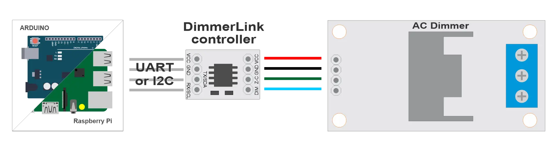
Connect
Plug DimmerLink output onto your TRIAC dimmer header. Connect VCC, GND, TX/RX (UART) or SDA/SCL (I2C) to your MCU.
2
Send a command
Write one byte to register 0x10 over I2C, or send a 3-byte UART packet. That's the entire API.
3
Done
DimmerLink fires the TRIAC at exactly the right moment. No ISR. No timer. No flickering. Every time.
Quick start — pick your platform
I2C mode — connect SDA/SCL, write one byte.
ESPHome YAML
i2c:
  sda: GPIO21
  scl: GPIO22

output:
  - platform: template
    id: dimmer_out
    type: float
    write_action:
      - i2c.write:
          address: 0x50
          register: 0x10
          data: !lambda 'return (int)(state * 100);'

light:
  - platform: monochromatic
    output: dimmer_out
    name: "AC Dimmer"
Tasmota Berry
import wire

def set_dim(level)  # 0–100
  wire.beginTransmission(0x50)
  wire.write(0x10)
  wire.write(level)
  wire.endTransmission()
end

set_dim(75)  # set to 75%
MicroPython
from machine import I2C, Pin

i2c = I2C(0, sda=Pin(21), scl=Pin(22))

def set_dim(level):  # 0–100
    i2c.writeto_mem(0x50, 0x10, bytes([level]))

set_dim(75)  # set to 75%
Raspberry Pi Python
import smbus2

bus = smbus2.SMBus(1)

def set_dim(level):  # 0–100
    bus.write_byte_data(0x50, 0x10, level)

set_dim(75)  # set to 75%
UART mode also available — 3-byte protocol, no library required.
UART Protocol Docs Full DocumentationThe entire API in one table
I2C address: 0x50 · Speed: 100 kHz
| Register | Name | Range | Description |
|---|---|---|---|
0x10 |
DIM0_LEVEL | 0 – 100 | Channel 0 brightness, percent |
0x11 |
DIM0_CURVE | 0 / 1 / 2 | 0 = LINEAR · 1 = RMS · 2 = LOG (perceptual) |
0x20 |
AC_FREQ | read-only | Detected mains frequency (50 / 60 Hz) |
Multi-channel registers (2CH/4CH): 0x10–0x13 for levels, 0x14–0x17 for curves. See full register map.
Choose your variant
Same protocol, same simplicity — from 1 channel to 4.
DimmerLink 1CH
Plug-in module for any RBDimmer 1-channel board
- ✓ UART + I2C
- ✓ 18 × 12 mm
- ✓ 1.8V / 3.3V / 5V
DimmerLink 2CH
Controls 2 channels simultaneously — one bus
- ✓ UART + I2C
- ✓ Fits RBDimmer 2CH header
- ✓ Independent curves per channel
DimmerLink 4CH
4 channels, 2 wires — no GPIO jungle
- ✓ UART + I2C
- ✓ Fits RBDimmer 4CH header
- ✓ Replaces 4 GPIO + 4 HW timers
4A / 8A + DimmerLink
Dimmer with DimmerLink soldered in — nothing extra to buy
- ✓ Same footprint as Standard
- ✓ Z-C/DIM pins replaced by UART/I2C
- ✓ Drop-in upgrade for existing wiring
Built for real projects
When your MCU is already busy doing something important.
☀️
Solar Router
PID control loop on ESP32, DimmerLink handles TRIAC — no timer conflicts with WiFi telemetry.
🔥
Reflow Oven
Temperature curve running on ESP32, DimmerLink fires the heating element — deterministic, jitter-free.
🏠
Home Assistant
3 lines of ESPHome YAML. DimmerLink runs autonomously — OTA updates don't interrupt dimming.
☕
Coffee Roaster
4CH dimmer + DimmerLink 4CH = 4 heating zones over one I2C bus. Arduino handles the roast profile.
Stop fighting timers.
Start building.
DimmerLink ships in UART mode. Switch to I2C any time with a single command — no reboot required.