← Getting Started | Contenido | Siguiente: Comunicación UART →
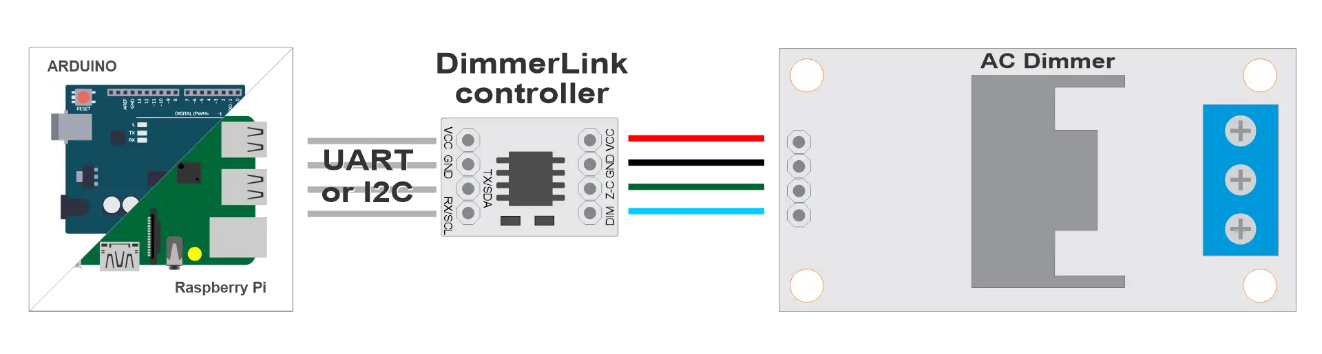
Conexión de hardware
Diagramas de cableado para conectar DimmerLink a microcontroladores y computadoras de placa única populares.
Conectores de DimmerLink
Conector de entrada (a su proyecto)
| Pin | Función | Descripción |
|---|---|---|
| VCC | Alimentación | 1.8V, 3.3V o 5V DC |
| GND | Tierra | Tierra común |
| TX/SDA | Datos | UART TX o I2C SDA |
| RX/SCL | Reloj | UART RX o I2C SCL |
Conector de salida (al módulo dimmer)
| Pin | Función | Descripción |
|---|---|---|
| VCC | Alimentación | Igual que la entrada |
| GND | Tierra | Tierra común |
| Z-C | Cruce por cero | Señal de cruce por cero |
| Dim | Control | Señal de compuerta TRIAC |
Compatibilidad
DimmerLink soporta un amplio rango de voltajes de alimentación y niveles lógicos:
| Voltaje | Alimentación VCC | Niveles lógicos |
|---|---|---|
| 1.8V | ✓ | ✓ |
| 3.3V | ✓ | ✓ |
| 5.0V | ✓ | ✓ |
✅ ¡Conexión directa a cualquier microcontrolador sin conversores de nivel!
Diagrama de conexión general
┌─────────────────┐      ┌──────────────────┐      ┌─────────┐      ┌──────┐
│  Your Project   │      │   DimmerLink     │      │ Dimmer  │      │ Lamp │
│  (Arduino/RPi)  │◄────►│                  │◄────►│ (TRIAC) │◄────►│      │
└─────────────────┘      └──────────────────┘      └─────────┘      └──────┘
     UART/I2C                                         AC 220V
Plataformas compatibles
DimmerLink funciona con cualquier microcontrolador que tenga interfaz UART o I2C.
| Plataforma | UART | I2C | Nivel lógico | Conexión |
|---|---|---|---|---|
| Arduino Uno/Nano | ✓ | ✓ | 5V | Directa |
| Arduino Mega | ✓ | ✓ | 5V | Directa |
| Arduino Due | ✓ | ✓ | 3.3V | Directa |
| ESP8266 | ✓ | ✓ | 3.3V | Directa |
| ESP32 | ✓ | ✓ | 3.3V | Directa |
| STM32 Blue Pill | ✓ | ✓ | 3.3V | Directa |
| Raspberry Pi Pico | ✓ | ✓ | 3.3V | Directa |
| Raspberry Pi 3/4/5 | ✓ | ✓ | 3.3V | Directa |
| Orange Pi | ✓ | ✓ | 3.3V | Directa |
| Banana Pi | ✓ | ✓ | 3.3V | Directa |
| ATtiny, nRF52, MSP430 | ✓ | ✓ | 1.8V | Directa |
¡Cualquier controlador con UART o I2C se conecta directamente!
Conexión I2C
Requisitos
- Resistencias pull-up: Muchos controladores ya tienen pull-ups I2C integrados. Añada resistencias de 4,7 kΩ en SDA y SCL hacia VCC
- Velocidad: 100 kHz (Standard Mode)
- Dirección: 0x50
Diagrama de cableado I2C
                    VCC (your board)
                     │
                ┌────┴────┐
               4.7kΩ     4.7kΩ
                │         │
┌───────────┐   │         │   ┌──────────────────┐
│           │   │         │   │   DimmerLink     │
│   Your    │───┴─────────│───│ SDA              │
│  Project  │             │   │                  │
│   SDA     │─────────────┴───│ SCL              │
│   SCL     │                 │                  │
│   GND     │─────────────────│ GND              │
│   VCC     │─────────────────│ VCC              │
└───────────┘                 └──────────────────┘
Conexión del dimmer
| DimmerLink | Dimmer | Descripción |
|---|---|---|
| VCC | VCC | Alimentación (igual que del MCU) |
| GND | GND | Tierra común |
| Z-C | Z-C (Zero Cross) | Señal de cruce por cero |
| Dim | DIM / PWM / Gate | Señal de control TRIAC |
Arduino Uno / Nano
Conexión I2C
| Arduino | DimmerLink |
|---|---|
| A4 (SDA) | SDA |
| A5 (SCL) | SCL |
| GND | GND |
| 5V | VCC |
Conexión UART
| Arduino | DimmerLink |
|---|---|
| TX (1) o SoftwareSerial | RX |
| RX (0) o SoftwareSerial | TX |
| GND | GND |
| 5V | VCC |
📝 Nota: En Arduino Uno, los pines 0/1 se usan para USB. Se recomienda usar SoftwareSerial.
#include
SoftwareSerial dimmerSerial(10, 11);  // RX, TX

void setup() {
    dimmerSerial.begin(115200);
}
Arduino Mega
Conexión I2C
| Arduino Mega | DimmerLink |
|---|---|
| 20 (SDA) | SDA |
| 21 (SCL) | SCL |
| GND | GND |
| 5V | VCC |
Conexión UART
| Arduino Mega | DimmerLink |
|---|---|
| TX1 (18) | RX |
| RX1 (19) | TX |
| GND | GND |
| 5V | VCC |
Arduino Mega tiene 4 UART por hardware (Serial, Serial1, Serial2, Serial3).
ESP8266 (NodeMCU, Wemos D1)
Conexión I2C
| ESP8266 | DimmerLink |
|---|---|
| D2 (GPIO4) | SDA |
| D1 (GPIO5) | SCL |
| GND | GND |
| 3.3V | VCC |
Conexión UART
| ESP8266 | DimmerLink |
|---|---|
| TX (GPIO1) | RX |
| RX (GPIO3) | TX |
| GND | GND |
| 3.3V | VCC |
📝 Note: GPIO1/GPIO3 are used for USB. Alternatives:
- UseSerial.swap()to remap to GPIO15/GPIO13
- Or use I2C instead of UART
ESP32
Conexión I2C
| ESP32 | DimmerLink |
|---|---|
| GPIO21 | SDA |
| GPIO22 | SCL |
| GND | GND |
| 3.3V | VCC |
Los pines I2C se pueden reasignar:
Wire.begin(SDA_PIN, SCL_PIN);
Conexión UART
| ESP32 | DimmerLink |
|---|---|
| GPIO17 (TX2) | RX |
| GPIO16 (RX2) | TX |
| GND | GND |
| 3.3V | VCC |
ESP32 tiene 3 UART por hardware (Serial, Serial1, Serial2).
STM32 Blue Pill
Conexión I2C
| STM32 | DimmerLink |
|---|---|
| PB7 (I2C1 SDA) | SDA |
| PB6 (I2C1 SCL) | SCL |
| GND | GND |
| 3.3V | VCC |
Conexión UART
| STM32 | DimmerLink |
|---|---|
| PA9 (USART1 TX) | RX |
| PA10 (USART1 RX) | TX |
| GND | GND |
| 3.3V | VCC |
Raspberry Pi Pico
Conexión I2C
| Pico | DimmerLink |
|---|---|
| GP4 (I2C0 SDA) | SDA |
| GP5 (I2C0 SCL) | SCL |
| GND | GND |
| 3V3 | VCC |
Conexión UART
| Pico | DimmerLink |
|---|---|
| GP0 (UART0 TX) | RX |
| GP1 (UART0 RX) | TX |
| GND | GND |
| 3V3 | VCC |
Raspberry Pi 3/4/5
Conexión I2C
| Raspberry Pi | DimmerLink |
|---|---|
| GPIO2 (Pin 3) | SDA |
| GPIO3 (Pin 5) | SCL |
| GND (Pin 6) | GND |
| 3.3V (Pin 1) | VCC |
Habilitar I2C:
sudo raspi-config
# Interface Options → I2C → Enable
Conexión UART
| Raspberry Pi | DimmerLink |
|---|---|
| GPIO14 (Pin 8) | RX |
| GPIO15 (Pin 10) | TX |
| GND (Pin 6) | GND |
| 3.3V (Pin 1) | VCC |
Habilitar UART:
sudo raspi-config
# Interface Options → Serial Port → Enable
Orange Pi / Banana Pi
La conexión es similar a Raspberry Pi, pero los números de GPIO pueden diferir.
Orange Pi (ej.: Orange Pi Zero)
⚠️ Warning: GPIO pinout differs between models! Check your specific board's documentation.
General principle: 1. Find I2C pins in your board's documentation 2. Connect SDA → SDA, SCL → SCL 3. Add 4.7kΩ pull-up resistors
| Orange Pi | DimmerLink |
|---|---|
| PA12 (TWI0-SDA) | SDA |
| PA11 (TWI0-SCL) | SCL |
| GND | GND |
| 3.3V | VCC |
Banana Pi (ej.: Banana Pi M2)
| Banana Pi | DimmerLink |
|---|---|
| GPIO2 (Pin 3) | SDA |
| GPIO3 (Pin 5) | SCL |
| GND | GND |
| 3.3V | VCC |
📝 Nota: Consulte la documentación de su modelo específico de Orange Pi / Banana Pi.
Resistencias pull-up I2C
Para un funcionamiento fiable del I2C, se requieren resistencias pull-up.
Cuándo se necesitan pull-ups externos
| Placa | Pull-ups integrados | Recomendación |
|---|---|---|
| Arduino | Débiles (~50 kΩ) | Funciona con cables cortos, pero se recomiendan 4,7 kΩ |
| ESP8266/ESP32 | Débiles | Añadir 4,7 kΩ externos |
| Raspberry Pi | Tiene 1,8 kΩ | Generalmente suficiente |
| STM32 | Ninguno | Es necesario añadir externos |
Cálculo del valor
- Cables cortos (< 10 cm): 4,7 kΩ – 10 kΩ
- Cables medios (10–50 cm): 2,2 kΩ – 4,7 kΩ
- Cables largos (> 50 cm): 1 kΩ – 2,2 kΩ (no recomendado)
Recomendaciones de instalación
- Mantenga los cables cortos — El I2C es sensible a la longitud, mantenga los cables por debajo de 30 cm
- Blindaje — Para distancias largas, use cable blindado
- Alimentación separada — Use una fuente de alimentación separada para DimmerLink si la fuente principal es inestable
- Desacoplamiento — Añada un condensador de 100 nF entre VCC y GND cerca de DimmerLink
Conexión a otros controladores
DimmerLink funciona con cualquier microcontrolador que tenga UART o I2C:
- PIC: Conexión a MSSP (I2C) o EUSART (UART)
- AVR (ATmega, ATtiny): TWI para I2C, USART para UART
- MSP430: Módulos eUSCI
- nRF52: Periféricos TWIM/UARTE
- RISC-V (ESP32-C3, GD32VF103): I2C/UART estándar
General principle: 1. Find I2C/UART pins in documentation 2. Connect according to tables above 3. Add pull-ups for I2C 4. Done!
← Getting Started | Contenido | Siguiente: Comunicación UART →