← ESPHome Component | Contents | Next: Arduino IDE Library →
TRIAC AC Dimmer Configuration Guide for Tasmota
This guide explains how to configure and use a TRIAC-based AC dimmer with Tasmota firmware for controlling 230V AC loads such as incandescent lamps, halogen lights, heaters, and other resistive loads.
Overview
A TRIAC (Triode for Alternating Current) dimmer allows you to control the power delivered to AC loads by cutting portions of each AC half-cycle. This is known as phase-cut dimming or leading edge dimming.
How It Works
The dimmer operates by detecting when the AC voltage crosses zero (Zero-Cross Detection) and then delaying the TRIAC trigger pulse. The longer the delay, the less power is delivered to the load:
- 0% dimming: TRIAC fires immediately after zero-cross → full power
- 50% dimming: TRIAC fires at mid-cycle → half power
- 100% dimming: TRIAC never fires → no power
The Tasmota implementation is power-calibrated, meaning 10% dimmer setting results in approximately 10% power consumption. This makes it ideal for applications like directing excess solar energy into a water heater or heat sink.
Typical Applications
- Dimming incandescent and halogen lamps
- Controlling resistive heaters
- Regulating fan speed (universal motors)
- Solar energy diversion to heat sinks
- Any resistive AC load control
Hardware Requirements
Components Needed
- ESP8266 or ESP32 board with Tasmota firmware installed
- TRIAC Dimmer Module with Zero-Cross detection output
Popular ready-made modules include:
- RBdimmer AC Dimmer Module (1 or 4 channel)
- Similar modules based on BTA16/BT136 TRIAC with MOC3021 optocoupler
Module Connections
A typical TRIAC dimmer module has the following connections:
| Module Pin | Description |
|---|---|
| VCC | Power supply (3.3V or 5V depending on module) |
| GND | Ground (common with ESP) |
| ZC | Zero-Cross detection output pulse |
| PWM | Dimmer control input |
| AC IN | Mains input (Live and Neutral) |
| AC OUT | Load output (to lamp/heater) |
Example Schematic
┌─────────────────────┐
                    │   TRIAC Dimmer      │
                    │      Module         │
    ┌───────────────┤                     ├───────────────┐
    │               │  ┌───┐    ┌───┐     │               │
 AC Line ──────────►│  │ZC │    │PWM│     │◄────────── AC Load
 (230V)             │  │Det│    │In │     │            (Lamp)
    │               │  └─┬─┘    └─┬─┘     │               │
 Neutral ──────────►│    │        │       │◄──────────────┘
                    │    │        │       │
                    └────┼────────┼───────┘
                         │        │
                         │        │
                    ┌────┴────────┴───────┐
                    │   ESP8266/ESP32     │
                    │                     │
                    │  GPIO14 ◄───── ZC   │
                    │  GPIO12 ─────► PWM  │
                    │                     │
                    │  VCC ◄───── 3.3V    │
                    │  GND ◄───── GND     │
└─────────────────────┘Tasmota Configuration
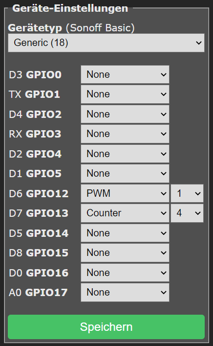
Step 1: GPIO Assignment
Configure the GPIO pins in Tasmota's web interface:
- Navigate to Configuration → Configure Module
- Set the following GPIO assignments:
| Function | GPIO Component | Description |
|---|---|---|
| Zero-Cross | Counter4 |
Receives ZC pulses from dimmer module |
| Dimmer Control | PWM1 |
Controls TRIAC firing delay |
Example configuration (using GPIO14 for ZC and GPIO12 for PWM):
| GPIO | Component |
|---|---|
| GPIO12 | PWM1 |
| GPIO14 | Counter4 |
After setting the GPIOs, click Save and allow the device to restart.
Step 2: Essential Commands
Before physically connecting the Zero-Cross and PWM signals, enter the following commands in the Tasmota Console:
SetOption99 1
SetOption99 1Enables detection of the rising edge of the zero-crossing signal. This is required for proper synchronization with the AC waveform.
LedTable 0
LedTable 0Disables gamma correction. For lamps and heaters, you want a linear power response where 50% dimmer = 50% power. Gamma correction is designed for LED perception and would distort the power curve.
SaveData 0
SaveData 0Disables periodic saving of dimmer state to flash memory. This prevents flickering that can occur during save operations. Especially recommended for ESP32.
Step 3: Additional Options (Multi-Channel Setup)
If you are using multiple PWM channels (e.g., a 4-channel dimmer module), also execute:
SetOption68 1This enables independent channel control. Each PWM channel operates as a separate light that can be controlled individually using Channel1, Channel2, etc.
Configuration Summary
Run these commands in sequence before connecting hardware:
SetOption99 1
LedTable 0
SaveData 0
For multi-channel setups, add:
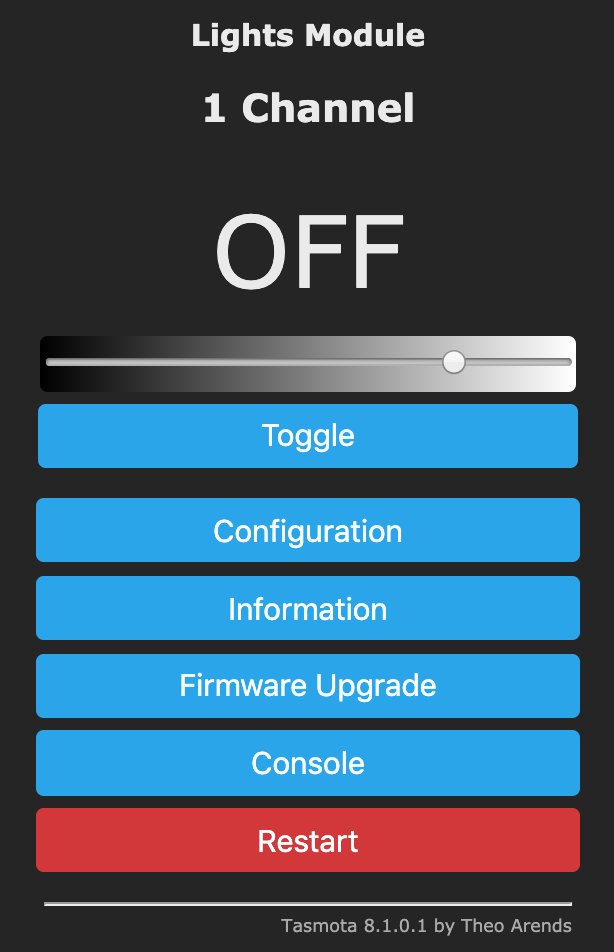
SetOption68 1Operating the Dimmer
Basic Commands
| Command | Range | Description |
|---|---|---|
Power |
ON/OFF/TOGGLE | Turn the dimmer output on or off |
Power 0 |
- | Turn off |
Power 1 |
- | Turn on |
Power 2 |
- | Toggle |
Dimmer |
0-100 | Set brightness/power level in percent |
Dimmer 50 |
- | Set to 50% power |
Dimmer +10 |
- | Increase by 10% |
Dimmer -10 |
- | Decrease by 10% |
Channel Control (Multi-Channel)
When SetOption68 1 is enabled:
| Command | Description |
|---|---|
Channel1 0..100 |
Control first dimmer channel |
Channel2 0..100 |
Control second dimmer channel |
Channel3 0..100 |
Control third dimmer channel |
Channel4 0..100 |
Control fourth dimmer channel |
Fade and Speed Effects
| Command | Range | Description |
|---|---|---|
Fade |
0/1 | Enable (1) or disable (0) smooth transitions |
Fade 1 |
- | Enable gradual dimming |
Speed |
1-40 | Transition speed (1=fastest, 40=slowest) |
Speed 5 |
- | Set medium-fast transition |
Example sequence for smooth dimming:
Fade 1
Speed 10
Dimmer 75
Calibration Command
ZCDimmerSetThis command is used for calibrating the zero-cross dimmer timing. Refer to Tasmota documentation for specific calibration procedures if you experience timing issues.
Troubleshooting
Light Flickers or Unstable
Possible causes and solutions:
- SaveData enabled: Run
SaveData 0to disable periodic flash writes - Poor Zero-Cross signal: Check wiring, ensure solid connections
- Incorrect SetOption99: Verify
SetOption99 1is set - WiFi interference: Try
SetOption65 1to reduce WiFi sleep transitions
Light Does Not Respond to Dimmer Commands
- Verify GPIO configuration matches your wiring
- Check that
Counter4is assigned to the Zero-Cross pin - Ensure the TRIAC module is receiving proper AC power
- Test with
Power 1first to verify basic connectivity
Dimmer Range Too Narrow
Some loads may not dim smoothly across the full 0-100% range. You can adjust the effective dimming range:
DimmerRange 10,100This sets minimum dimmer at 10% and maximum at 100%. Adjust the minimum value until the load operates reliably at low settings.
Light is Very Dark Even at Higher Dimmer Values
If using LedTable 1 (gamma correction enabled), the response curve is non-linear. For resistive loads:
LedTable 0ESP32 Specific: Flickering During WiFi Activity
On ESP32, enable the following for more stable operation:
SaveData 0
SetOption65 1
Safety Considerations
Critical Safety Requirements:
- Always disconnect mains power before making any wiring changes
- Use appropriate enclosures - never leave mains-voltage circuits exposed
- Verify load compatibility - TRIAC dimmers work best with resistive loads
- Do not exceed current ratings of your TRIAC module
- Ensure proper grounding of all equipment
- Use appropriate wire gauges for the current being switched
- Install appropriate fuses or circuit breakers upstream of the dimmer
Load Compatibility
| Load Type | Compatibility | Notes |
|---|---|---|
| Incandescent lamps | ✓ Excellent | Ideal load type |
| Halogen lamps | ✓ Excellent | Ideal load type |
| Resistive heaters | ✓ Excellent | Great for solar diversion |
| Dimmable LED lamps | △ Check specs | Must be "leading edge" compatible |
| Non-dimmable LED | ✗ No | Will flicker or be damaged |
| Fluorescent/CFL | ✗ No | Not compatible |
| Motors (inductive) | △ Limited | Only universal motors, with caution |
| Transformers | ✗ No | Can cause overheating |
Quick Reference Card
Initial Setup Commands
SetOption99 1    ; Enable ZC rising edge detection
LedTable 0       ; Linear power response
SaveData 0       ; Prevent flicker from flash writes
SetOption68 1    ; Multi-channel independence (if needed)
Daily Operation
Power ON         ; Turn on
Power OFF        ; Turn off
Dimmer 50        ; Set to 50%
Dimmer +10       ; Increase 10%
Dimmer -10       ; Decrease 10%
Channel1 75      ; Set channel 1 to 75%
Smooth Transitions
Fade 1           ; Enable fading
Speed 10         ; Set transition speed
Dimmer 100       ; Fade to full brightness
References
- Tasmota Lights Documentation
- Tasmota Commands Reference
- SetOption99 Documentation
- AC Dimmer Module on rbdimmer.com
← ESPHome Component | Contents | Next: Arduino IDE Library →